1. Why Do Lithium Batteries Need Protection?
Lithium batteries, especially lithium-ion and lithium polymer batteries, offer advantages like high energy density and light weight. However, they are very sensitive to usage conditions:
Overcharge: Can lead to increased internal pressure, heating, and even fire or explosion.
Over-discharge: Can permanently damage the battery, causing a severe and irreversible capacity drop.
Overcurrent/Short Circuit: Generates significant heat, potentially triggering thermal runaway, which is an extremely dangerous situation.
Therefore, any lithium battery pack (from phones to electric vehicles) must be equipped with a Battery Protection Circuit Board (BMS or Protection Board).
2. Classic Architecture of a Lithium Battery Protection Board
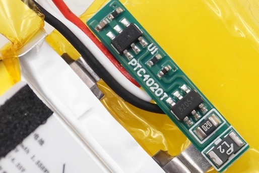
A typical lithium battery protection circuit generally includes the following core components:
Protection IC: This is the "brain" of the protection board. It monitors the battery's voltage (to prevent overcharge/over-discharge) and current (indirectly determined by measuring the voltage drop across the MOSFETs) in real-time.
MOSFET Switches: These are the "actuators" of the protection board. They turn the charge/discharge circuit on or off based on commands from the Protection IC. Typically, two MOSFETs are connected back-to-back to control charging and discharging separately.
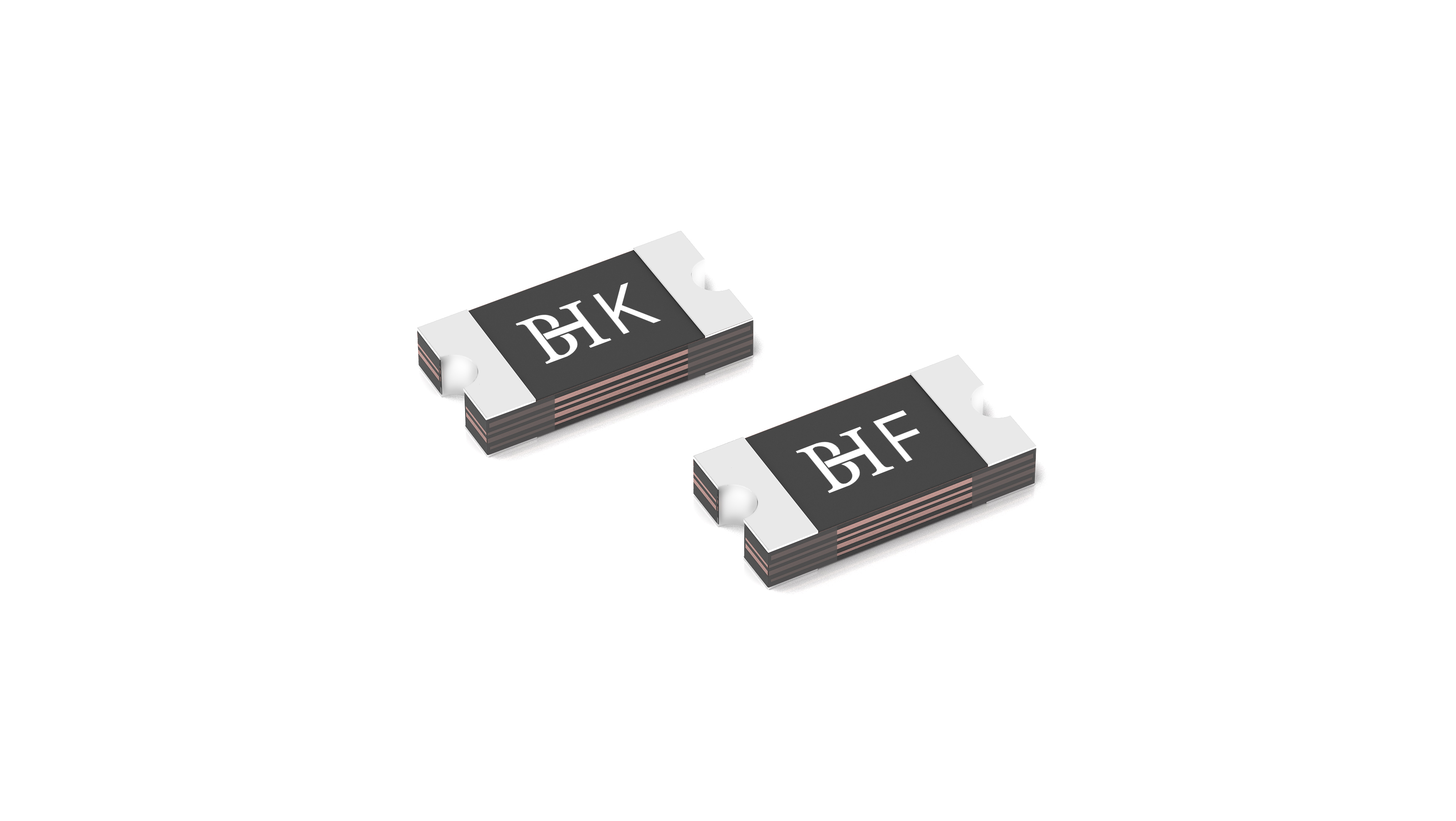
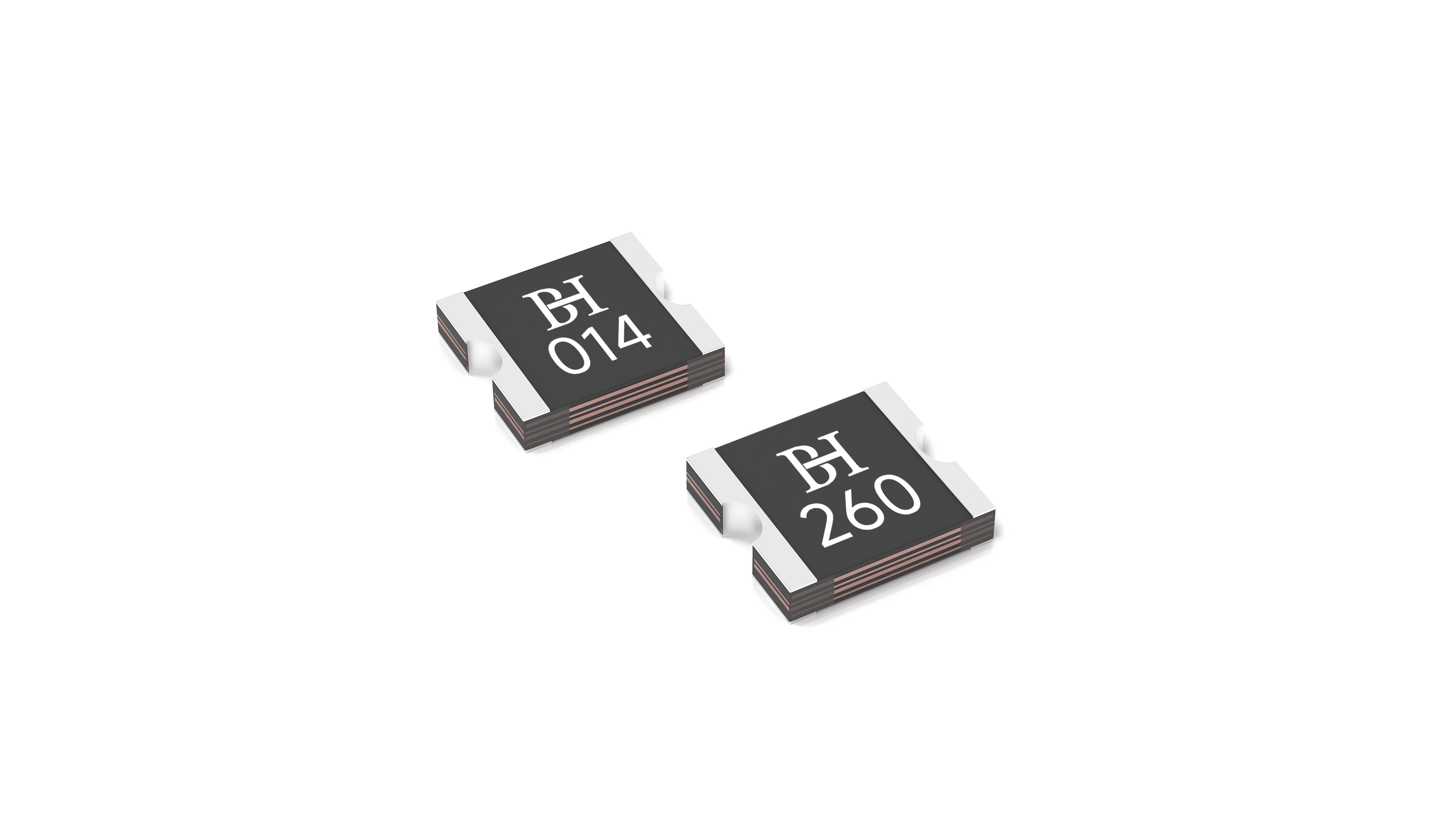
PPTC: This acts as a "Resettable Fuse" and "Temperature Sensor" for the protection board. It works in conjunction with the Protection IC and MOSFETs, providing a secondary line of defense.
3. Specific Roles and Advantages of PPTC in Lithium Battery Protection
The core characteristic of a PPTC is: low resistance at normal temperatures; when the current flowing through it is too high or the ambient temperature rises, it self-heats causing a rapid temperature increase, and its resistance non-linearly increases sharply (referred to as "tripping" or "activation"), effectively limiting the current in the circuit. When the fault is cleared and the current ceases, the PPTC cools down, its resistance returns to a low state, and the circuit resumes normal operation.
In lithium battery protection, PPTC primarily provides two key types of protection:
1. Overcurrent and Short Circuit Protection
Working Principle:
Under normal discharge current, the PPTC remains in a low-resistance state (typically only a few milliohms), having minimal impact on the circuit.
When an abnormal load causes excessive current or a short circuit occurs, the high current rapidly heats the PPTC, causing it to trip and limit the current to a very low level (typically just a few milliamps to tens of milliamps).
This functions as a resettable fuse, preventing battery damage, swelling, or hazardous situations due to sustained high-current discharge.
Synergy with Protection IC/MOSFET:
The Protection IC can also detect overcurrent and shut off the MOSFETs. However, the MOSFETs endure significant stress, with a risk of breakdown, at the moment of interrupting a high current (especially a short-circuit current).
Although the PPTC's response speed is slower than the MOSFETs, it can absorb and dissipate a large amount of energy, sharing the stress on the MOSFETs and enhancing the overall reliability of the protection system. Even if the MOSFETs fail to turn off in time, the PPTC acts as a backup protection.
After a short-circuit fault is resolved, the PPTC can reset automatically, whereas a traditional fuse would require manual replacement.
2. Overtemperature Protection
This is a very unique and important function of the PPTC.
Working Principle:
The PPTC's activation is triggered by temperature, which comes from its self-heating (caused by overcurrent) and/or the external ambient temperature.
If the battery temperature rises abnormally due to internal defects, a high external ambient temperature, or tight enclosure within a device, even if the current is within limits, the PPTC can sense the rise in ambient temperature. When the temperature reaches its activation point (e.g., 85°C, 105°C, etc.), it will also transition from a low-resistance to a high-resistance state.
Importance:
Lithium batteries operating at high temperatures are extremely dangerous, accelerating aging and failure processes.
Traditional Protection ICs and MOSFETs primarily monitor electrical parameters (voltage, current) and have limited or require additional sensors for sensing the battery's core temperature.
When the PPTC is physically installed in close contact with the battery, it acts as a direct, passive temperature sensor and switch, cutting off the circuit when the battery temperature becomes too high, providing crucial thermal protection.
4. PPTC Placement in Applications
In actual battery protection boards or battery packs, PPTCs are commonly placed in two ways:
Series Connection in the Main Circuit:
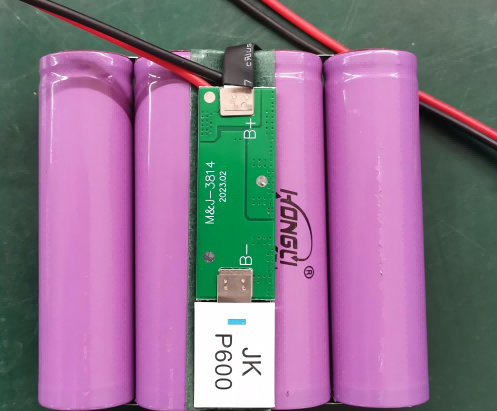
This is the most common method. The PPTC is directly connected in series with the battery's positive or negative output terminal. It provides protection against both overcurrent and external high temperatures.
Placed before the MOSFETs in conjunction with the Protection IC:
This layout better protects the MOSFETs from high current surges.
5. Limitations of PPTC
Although PPTCs are very useful, they have limitations and need to be used in conjunction with Protection ICs and MOSFETs to form a comprehensive protection system:
Cannot Prevent Overcharge: PPTCs cannot detect voltage, so they cannot prevent overcharge caused by charger faults. This is the responsibility of the Protection IC.
Has a Rated Voltage Limit: PPTCs have a maximum operating voltage. Selection must ensure this is higher than the battery pack's maximum voltage (e.g., voltage when fully charged).
Has Internal Resistance and Voltage Drop: Even in the non-triggered state, the PPTC's low resistance can cause a certain voltage drop and power loss under very high currents.
Requires Cool-Down Time After Activation: After tripping, it cannot reset immediately and requires time to cool down. This might not be suitable for applications with frequent pulsed discharges.
Hold Current vs. Trip Current: Precise selection is required based on the device's maximum normal operating current (Hold Current) and the overcurrent value requiring protection (Trip Current).
Summary
The PPTC resettable fuse is an indispensable, multi-functional passive protection component in lithium battery protection. Its core value lies in:
Providing resettable overcurrent and short circuit protection, eliminating the hassle of replacing fuses. Providing unique, passive overtemperature protection, directly responding to abnormal rises in battery or ambient temperature. Working synergistically with the active Protection IC/MOSFET system, serving as a reliable physical barrier, enhancing the robustness and safety of the entire battery protection system.
Therefore, PPTCs can be found in almost all consumer electronics lithium battery packs, such as mobile phones, laptops, Bluetooth headsets, power banks, etc.